Mercedes AMG Power Wheeler: Difference between revisions
Jump to navigation
Jump to search
Tag: visualeditor |
m →Code |
||
| (14 intermediate revisions by the same user not shown) | |||
| Line 4: | Line 4: | ||
{{Component| URUAV 550 12V Electric Reducer Gear Case with Motor for Kids Children Ride On Car}} | {{Component| URUAV 550 12V Electric Reducer Gear Case with Motor for Kids Children Ride On Car}} | ||
* https://www.thingiverse.com/thing:3001523 | |||
* Current consumtion nominal: 2A | * Current consumtion nominal: 2A | ||
== Controller upgrade == | == Controller upgrade == | ||
[[File:Control-schematic-car.PNG|center]] | |||
Tachometer install | |||
* red - 12V | |||
* green signal wire 3000rpm = 6.23Hz 10V offset 5V duty 20% range = 3.9Hz - 6.7hz | |||
* black - gnd | |||
* yellow - 12v | |||
[[File:Tacho-wave.png|thumb|Downloaded from banggood|center]] | |||
=== Code new === | |||
-- relay 1 input | |||
gpio.mode(6, gpio.INPUT, gpio.PULLUP ) | |||
-- relay 2 input | |||
gpio.mode(7, gpio.INPUT, gpio.PULLUP ) | |||
-- power switch control output | |||
gpio.mode(5, gpio.OUTPUT ) | |||
-- relay 1 ouput | |||
gpio.mode(2, gpio.OUTPUT ) | |||
-- relay 2 ouput | |||
gpio.mode(1, gpio.OUTPUT ) | |||
relay1 = 0 | |||
relay2 = 0 | |||
function toggle_output_pwm() | |||
gpio.write(1, gpio.HIGH) | |||
tmr.delay(10000) | |||
gpio.write(1, gpio.LOW) | |||
end | |||
function deactivate_pwm_output() | |||
gpio.write(5, gpio.LOW) | |||
tmr.delay(10000) | |||
end | |||
function activate_pwm_output() | |||
gpio.write(5, gpio.HIGH) | |||
tmr.delay(10000) | |||
end | |||
function on_success_callback() | |||
val = adc.read(0) | |||
if val < 10 then | |||
print("System voltage low (mV):", val) | |||
else | |||
print("System voltage high (mv):", val) | |||
end | |||
end | |||
function check_relay1_input() | |||
relay1_input = gpio.read(6) -- gpio12 | |||
relay2_input = gpio.read(7) -- gpio13 | |||
print("Status relay 1:", relay1_input) | |||
print("Status relay 2:", relay2_input) | |||
if relay1_input == 0 then | |||
-- trigger output low | |||
if relay1 == 0 then | |||
deactivate_pwm_output() | |||
end | |||
-- activate relay 1 | |||
relay1 = 1 | |||
gpio.write(2, gpio.HIGH) | |||
activate_pwm_output() | |||
elseif relay2_input == 0 then | |||
-- trigger output low | |||
if relay2 == 0 then | |||
deactivate_pwm_output() | |||
end | |||
-- activate relay 1 | |||
relay2 = 1 | |||
gpio.write(5, gpio.HIGH) | |||
activate_pwm_output() | |||
else | |||
-- trigger output low | |||
print("Deactivate outputs") | |||
deactivate_pwm_output() | |||
-- activate relay 1 | |||
relay1 = 0 | |||
relay2 = 0 | |||
gpio.write(2, gpio.LOW) | |||
gpio.write(5, gpio.LOW) | |||
end | |||
end | |||
function check_relay2_input() | |||
end | |||
-- if the output is active deactivate it | |||
val = adc.read(0) | |||
if val > 10 then | |||
print("Output is active:", val) | |||
toggle_output_pwm() | |||
val = adc.read(0) | |||
print("Output is deactivated:", val) | |||
end | |||
mytimer = tmr.create() | |||
mytimer:register(10000, tmr.ALARM_AUTO, on_success_callback) | |||
mytimer:interval(100) -- actually, 500 mseconds is better! | |||
mytimer:start() | |||
mytimer1 = tmr.create() | |||
mytimer1:register(10000, tmr.ALARM_AUTO, check_relay1_input) | |||
mytimer1:interval(100) -- actually, 500 mseconds is better! | |||
mytimer1:start() | |||
mytimer2 = tmr.create() | |||
mytimer2:register(10000, tmr.ALARM_AUTO, check_relay2_input) | |||
mytimer2:interval(500) -- actually, 500 mseconds is better! | |||
mytimer2:start() | |||
=== Code old === | |||
-- relay 1 input | |||
gpio.mode(6, gpio.INPUT, gpio.PULLUP ) | |||
-- relay 2 input | |||
gpio.mode(7, gpio.INPUT, gpio.PULLUP ) | |||
-- power switch control output | |||
gpio.mode(1, gpio.OUTPUT ) | |||
-- relay 1 ouput | |||
gpio.mode(2, gpio.OUTPUT ) | |||
-- relay 2 ouput | |||
gpio.mode(5, gpio.OUTPUT ) | |||
relay1 = 0 | |||
relay2 = 0 | |||
function toggle_output_pwm() | |||
gpio.write(1, gpio.HIGH) | |||
tmr.delay(10000) | |||
gpio.write(1, gpio.LOW) | |||
end | |||
function deactivate_pwm_output() | |||
val = adc.read(0) | |||
if val > 10 then | |||
print("Output is active:", val) | |||
toggle_output_pwm() | |||
val = adc.read(0) | |||
print("Output is deactivated:", val) | |||
end | |||
end | |||
function activate_pwm_output() | |||
val = adc.read(0) | |||
if val < 10 then | |||
print("Output is deactivated:", val) | |||
toggle_output_pwm() | |||
val = adc.read(0) | |||
print("Output is activated:", val) | |||
end | |||
end | |||
function on_success_callback() | |||
val = adc.read(0) | |||
if val < 10 then | |||
print("System voltage low (mV):", val) | |||
else | |||
print("System voltage high (mv):", val) | |||
end | |||
end | |||
function check_relay1_input() | |||
relay1_input = gpio.read(6) -- gpio12 | |||
relay2_input = gpio.read(7) -- gpio13 | |||
print("Status relay 1:", relay1_input) | |||
print("Status relay 2:", relay2_input) | |||
if relay1_input == 0 then | |||
-- trigger output low | |||
if relay1 == 0 then | |||
deactivate_pwm_output() | |||
end | |||
-- activate relay 1 | |||
relay1 = 1 | |||
gpio.write(2, gpio.HIGH) | |||
activate_pwm_output() | |||
elseif relay2_input == 0 then | |||
-- trigger output low | |||
if relay2 == 0 then | |||
deactivate_pwm_output() | |||
end | |||
-- activate relay 1 | |||
relay2 = 1 | |||
gpio.write(5, gpio.HIGH) | |||
activate_pwm_output() | |||
else | |||
-- trigger output low | |||
deactivate_pwm_output() | |||
-- activate relay 1 | |||
relay1 = 0 | |||
relay2 = 0 | |||
gpio.write(2, gpio.LOW) | |||
gpio.write(5, gpio.LOW) | |||
end | |||
end | |||
function check_relay2_input() | |||
end | |||
-- if the output is active deactivate it | |||
val = adc.read(0) | |||
if val > 10 then | |||
print("Output is active:", val) | |||
toggle_output_pwm() | |||
val = adc.read(0) | |||
print("Output is deactivated:", val) | |||
end | |||
mytimer = tmr.create() | |||
mytimer:register(10000, tmr.ALARM_AUTO, on_success_callback) | |||
mytimer:interval(500) -- actually, 500 mseconds is better! | |||
mytimer:start() | |||
mytimer1 = tmr.create() | |||
mytimer1:register(10000, tmr.ALARM_AUTO, check_relay1_input) | |||
mytimer1:interval(500) -- actually, 500 mseconds is better! | |||
mytimer1:start() | |||
mytimer2 = tmr.create() | |||
mytimer2:register(10000, tmr.ALARM_AUTO, check_relay2_input) | |||
mytimer2:interval(500) -- actually, 500 mseconds is better! | |||
mytimer2:start() | |||
{| class="wikitable" | {| class="wikitable" | ||
| colspan="6"|[[File:DR01 V2.6 power schematicv4.PNG|alt=DR01 V2.6 power schematic|center|Power schematic DR01 V2.6]] | |||
|- | |||
|+ | |+ | ||
!Component | !Component | ||
| Line 18: | Line 248: | ||
!Comments | !Comments | ||
!Color | !Color | ||
|- | |- | ||
|Power mosfet | |Power mosfet | ||
|NCE30H10K | |NCE30H10K | ||
| | |<pdf>File:NCE30H10K-NCEPowerSemiconductor.pdf</pdf> | ||
|{{Component| MOSFET High Power Heated Bed Expansion Power Module}} | |{{Component| MOSFET High Power Heated Bed Expansion Power Module}} | ||
| | | | ||
| Line 30: | Line 258: | ||
|Power relays | |Power relays | ||
|SANYOU SARM-S112D4 | |SANYOU SARM-S112D4 | ||
| | |<pdf>File:SANYOU_SARM-S112D4.pdf</pdf> | ||
|{{Component| 12V Relay 20A auto}} | |{{Component| 12V Relay 20A auto}} | ||
| | | | ||
|black | |black | ||
|} | |} | ||
== Speed control == | |||
Latest revision as of 11:40, 6 June 2021
| Mercedes AMG Power Wheeler |
|
| https://bogza.ro/index.php/Mercedes_AMG_Power_Wheeler | |


Power upgrade =
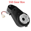
- Current consumtion nominal: 2A
Controller upgrade

Tachometer install
- red - 12V
- green signal wire 3000rpm = 6.23Hz 10V offset 5V duty 20% range = 3.9Hz - 6.7hz
- black - gnd
- yellow - 12v

Code new
-- relay 1 input
  gpio.mode(6, gpio.INPUT, gpio.PULLUP )
  -- relay 2 input
  gpio.mode(7, gpio.INPUT, gpio.PULLUP )
  -- power switch control output
  gpio.mode(5, gpio.OUTPUT )
  -- relay 1 ouput
  gpio.mode(2, gpio.OUTPUT )
  -- relay 2 ouput
  gpio.mode(1, gpio.OUTPUT )

  relay1 = 0
  relay2 = 0

  function toggle_output_pwm()
      gpio.write(1, gpio.HIGH)
      tmr.delay(10000)
      gpio.write(1, gpio.LOW)
  end

  function deactivate_pwm_output()
      gpio.write(5, gpio.LOW)
      tmr.delay(10000)
  end

  function activate_pwm_output()
      gpio.write(5, gpio.HIGH)
      tmr.delay(10000)
  end

  function on_success_callback()
      val = adc.read(0)
      if val < 10 then
             print("System voltage low (mV):", val)
      else
             print("System voltage high (mv):", val)
      end
  end

  function check_relay1_input()
      relay1_input = gpio.read(6) -- gpio12
      relay2_input = gpio.read(7) -- gpio13
      print("Status relay 1:", relay1_input)
      print("Status relay 2:", relay2_input)
      if relay1_input == 0 then
          -- trigger output low
          if relay1 == 0 then
              deactivate_pwm_output()
          end
          -- activate relay 1
          relay1 = 1
          gpio.write(2, gpio.HIGH)
          activate_pwm_output()
     elseif relay2_input == 0 then
          -- trigger output low
          if relay2 == 0 then
              deactivate_pwm_output()
          end
          -- activate relay 1
          relay2 = 1
          gpio.write(5, gpio.HIGH)
          activate_pwm_output()
     else
          -- trigger output low
          print("Deactivate outputs")
          deactivate_pwm_output()
          -- activate relay 1
          relay1 = 0
          relay2 = 0
          gpio.write(2, gpio.LOW)
          gpio.write(5, gpio.LOW)
     end
  end

  function check_relay2_input()

  end

  -- if the output is active deactivate it
  val = adc.read(0)
  if val > 10 then
         print("Output is active:", val)
         toggle_output_pwm()
         val = adc.read(0)
         print("Output is deactivated:", val)
  end

  mytimer = tmr.create()
  mytimer:register(10000, tmr.ALARM_AUTO, on_success_callback)
  mytimer:interval(100) -- actually, 500 mseconds is better!
  mytimer:start()

  mytimer1 = tmr.create()
  mytimer1:register(10000, tmr.ALARM_AUTO, check_relay1_input)
  mytimer1:interval(100) -- actually, 500 mseconds is better!
  mytimer1:start()

  mytimer2 = tmr.create()
  mytimer2:register(10000, tmr.ALARM_AUTO, check_relay2_input)
  mytimer2:interval(500) -- actually, 500 mseconds is better!
  mytimer2:start()
Code old
   -- relay 1 input
   gpio.mode(6, gpio.INPUT, gpio.PULLUP )
   -- relay 2 input
   gpio.mode(7, gpio.INPUT, gpio.PULLUP )
   -- power switch control output
   gpio.mode(1, gpio.OUTPUT )
   -- relay 1 ouput
   gpio.mode(2, gpio.OUTPUT )
   -- relay 2 ouput
   gpio.mode(5, gpio.OUTPUT )

   relay1 = 0
   relay2 = 0

   function toggle_output_pwm()
       gpio.write(1, gpio.HIGH)
       tmr.delay(10000)
       gpio.write(1, gpio.LOW)
   end

   function deactivate_pwm_output()
       val = adc.read(0)
       if val > 10 then
              print("Output is active:", val)
              toggle_output_pwm()
              val = adc.read(0)
              print("Output is deactivated:", val)
       end
   end

   function activate_pwm_output()
       val = adc.read(0)
       if val < 10 then
              print("Output is deactivated:", val)
              toggle_output_pwm()
              val = adc.read(0)
              print("Output is activated:", val)
       end
   end

   function on_success_callback()
       val = adc.read(0)
       if val < 10 then
              print("System voltage low (mV):", val)
       else
              print("System voltage high (mv):", val)
       end
   end

   function check_relay1_input()
       relay1_input = gpio.read(6) -- gpio12
       relay2_input = gpio.read(7) -- gpio13
       print("Status relay 1:", relay1_input)
       print("Status relay 2:", relay2_input)
       if relay1_input == 0 then
           -- trigger output low
           if relay1 == 0 then
               deactivate_pwm_output()
           end
           -- activate relay 1
           relay1 = 1
           gpio.write(2, gpio.HIGH)
           activate_pwm_output()
      elseif relay2_input == 0 then
           -- trigger output low
           if relay2 == 0 then
               deactivate_pwm_output()
           end
           -- activate relay 1
           relay2 = 1
           gpio.write(5, gpio.HIGH)
           activate_pwm_output()
      else
           -- trigger output low
           deactivate_pwm_output()
           -- activate relay 1
           relay1 = 0
           relay2 = 0
           gpio.write(2, gpio.LOW)
           gpio.write(5, gpio.LOW)
      end
   end

   function check_relay2_input()

   end

   -- if the output is active deactivate it
   val = adc.read(0)
   if val > 10 then
          print("Output is active:", val)
          toggle_output_pwm()
          val = adc.read(0)
          print("Output is deactivated:", val)
   end

   mytimer = tmr.create()
   mytimer:register(10000, tmr.ALARM_AUTO, on_success_callback)
   mytimer:interval(500) -- actually, 500 mseconds is better!
   mytimer:start()

   mytimer1 = tmr.create()
   mytimer1:register(10000, tmr.ALARM_AUTO, check_relay1_input)
   mytimer1:interval(500) -- actually, 500 mseconds is better!
   mytimer1:start()

   mytimer2 = tmr.create()
   mytimer2:register(10000, tmr.ALARM_AUTO, check_relay2_input)
   mytimer2:interval(500) -- actually, 500 mseconds is better!
   mytimer2:start()
 | |||||
| Component | Current part | Data sheet | Replacement power part | Comments | Color |
|---|---|---|---|---|---|
| Power mosfet | NCE30H10K | <pdf>File:NCE30H10K-NCEPowerSemiconductor.pdf</pdf> | 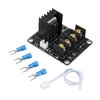 |
yellow | |
| Power relays | SANYOU SARM-S112D4 | <pdf>File:SANYOU_SARM-S112D4.pdf</pdf> | 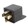 |
black | |