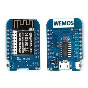
Geekcreit D1 mini V2.2.0 WIFI Internet Development Board Based ESP8266 4MB FLASH ESP-12S Chip: Difference between revisions
Jump to navigation
Jump to search
m (→Specifications) |
m (→Specifications) Tag: visualeditor |
||
| Line 29: | Line 29: | ||
[[File:D1-mini-pinout.jpg]] | [[File:D1-mini-pinout.jpg]] | ||
{| class="wikitable" | |||
|- | |||
|Label | |||
|GPIO | |||
|Input | |||
|Output | |||
|Notes | |||
|- | |||
|D0 | |||
|GPIO16 | |||
|no interrupt | |||
|no PWM or I2C support | |||
|HIGH at boot | |||
used to wake up from deep sleep | |||
|- | |||
|D1 | |||
|GPIO5 | |||
|OK | |||
|OK | |||
|often used as SCL (I2C) | |||
|- | |||
|D2 | |||
|GPIO4 | |||
|OK | |||
|OK | |||
|often used as SDA (I2C) | |||
|- | |||
|D3 | |||
|GPIO0 | |||
|pulled up | |||
|OK | |||
|connected to FLASH button, boot fails if pulled LOW | |||
|- | |||
|D4 | |||
|GPIO2 | |||
|pulled up | |||
|OK | |||
|HIGH at boot | |||
connected to on-board LED, boot fails if pulled LOW | |||
|- | |||
|D5 | |||
|GPIO14 | |||
|OK | |||
|OK | |||
|SPI (SCLK) | |||
|- | |||
|D6 | |||
|GPIO12 | |||
|OK | |||
|OK | |||
|SPI (MISO) | |||
|- | |||
|D7 | |||
|GPIO13 | |||
|OK | |||
|OK | |||
|SPI (MOSI) | |||
|- | |||
|D8 | |||
|GPIO15 | |||
|pulled to GND | |||
|OK | |||
|SPI (CS) | |||
Boot fails if pulled HIGH | |||
|- | |||
|RX | |||
|GPIO3 | |||
|OK | |||
|RX pin | |||
|HIGH at boot | |||
|- | |||
|TX | |||
|GPIO1 | |||
|TX pin | |||
|OK | |||
|HIGH at boot | |||
debug output at boot, boot fails if pulled LOW | |||
|- | |||
|A0 | |||
|ADC0 | |||
|Analog Input | |||
|X | |||
|} | |||
Latest revision as of 12:01, 29 December 2020
Specifications
| Geekcreit D1 mini V2.2.0 WIFI Internet Development Board Based ESP8266 4MB FLASH ESP-12S Chip |
|
| https://bogza.ro/index.php/Geekcreit_D1_mini_V2.2.0_WIFI_Internet_Development_Board_Based_ESP8266_4MB_FLASH_ESP-12S_Chip | |

Feature:
- 11 digital input/output pins, all pins have interrupt/pwm/I2C/one-wire supported(except D0)
- 1 analog input(3.2V max input)
- a Micro USB connection
Package included:
1 x D1 mini V2.2.0 2 x Long female pin 2 x Short female pin 2 x Normal pin
| Label | GPIO | Input | Output | Notes |
| D0 | GPIO16 | no interrupt | no PWM or I2C support | HIGH at boot
used to wake up from deep sleep |
| D1 | GPIO5 | OK | OK | often used as SCL (I2C) |
| D2 | GPIO4 | OK | OK | often used as SDA (I2C) |
| D3 | GPIO0 | pulled up | OK | connected to FLASH button, boot fails if pulled LOW |
| D4 | GPIO2 | pulled up | OK | HIGH at boot
connected to on-board LED, boot fails if pulled LOW |
| D5 | GPIO14 | OK | OK | SPI (SCLK) |
| D6 | GPIO12 | OK | OK | SPI (MISO) |
| D7 | GPIO13 | OK | OK | SPI (MOSI) |
| D8 | GPIO15 | pulled to GND | OK | SPI (CS)
Boot fails if pulled HIGH |
| RX | GPIO3 | OK | RX pin | HIGH at boot |
| TX | GPIO1 | TX pin | OK | HIGH at boot
debug output at boot, boot fails if pulled LOW |
| A0 | ADC0 | Analog Input | X |
