Microwave Radar Detector Module RCWL-0516
Features
| Microwave Radar Detector Module RCWL-0516 |
|
| https://bogza.ro/index.php/Microwave_Radar_Detector_Module_RCWL-0516 | |
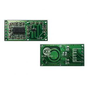
RCWL-0516 Microwave Radar Sensor Switch Module Human Induction Detector
RCWL-0516 microwave radar sensor switch module human sensor module intelligent sensor detector sensing distance of about 5-7 meters
Adjustment Part Introduction
C-TM
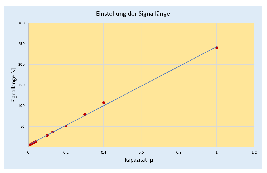
Adjust repeat trigger time,default trigger time is 2s;increasing capacitor's capacity will make repeat trigger time longer;and actual counting trigger time can operate as below:
Stick capacitor on C-TM,test 9196 3-pin frequency F,repeat trigger time T=(1/f)*32768

R-GN
Detection distance adjustment;connect with resistor and detection distance will become shorter;if not connect,detection distance is 7m;if connect with 1M ohm resistor,detection distance is 5m
- without resistor: ca. 6 Meter
- R-GN = 1 MΩ: ca. 4.5 Meter
- R-GN = 470 kΩ: ca. 2.5 Meter
- R-GN = 270 kΩ: ca. 1.5 Meter
- R-GN = 100 kΩ: 0 Meter (keine Bewegung wird erkannt)
R-CDS
Internal VCC parallel connect with internal 1M ohm resistor to CDS pin (that is 196 9-pin) by R-CDS ,CDS connects with photoresistor,you can close detection function at night
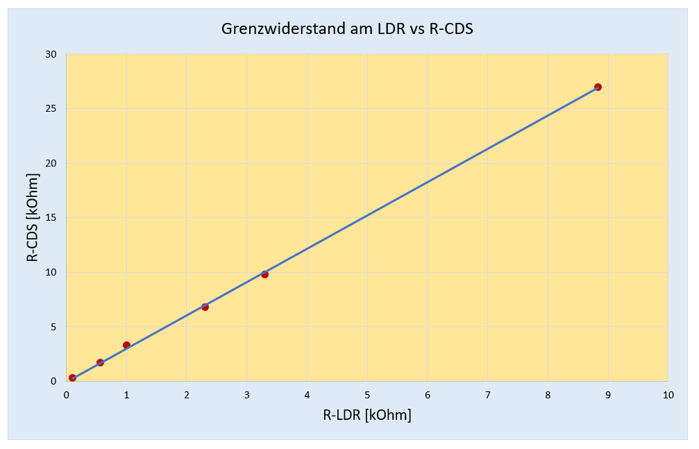
If you use the motion sensor to switch on a lamp, then it makes perfect sense to deactivate this function in daylight. As already mentioned, you either solder an LDR to the CDS connector on the module or you attach an LDR to the CDS pin. But that alone is not enough, because it deactivates your OUT even in the dark. You also have to attach a resistor to R-CDS. The size of this resistance determines at which brightness the OUT signal becomes active again.
In order to record this quantitatively, I connected various resistors to R-CDS and a potentiometer to CDS. Then I tested at which limit resistance OUT becomes active or inactive. Here, too, there was a linear relationship. The OUT pin becomes active (or inactive) when the LDR reaches a resistance that is around a third of the resistance at R-CDS.

Pin Definition
- 3V3:3V3 power output
- GND:ground
- OUT:control output;when detect moving objects,it will output high level
- VIN:input voltage,4-28V
- CDS:enable control chip,lower than 0.7V,OUT will output low level all the time

Specifications
| Parameter | Value |
|---|---|
| Operating Voltage | 4-28V |
| Operating Current | 2.8mA (typical);3mA (max) |
| Output Current | 3A(max) |
| Detection Distance | 5-9m |
| Transmitting Power | 20mW (typical);30mW (max) |
| Output Voltage | 3.2-3.4V |
| Output Voltage Driving Capacity | 100mA |
| Trigger Way | repeat trigger |
| Output Control Low Level | 0V |
| Output Control High Level | 3.3V |
| Operating Temperature | -20~80 celsius |
| Storage Temperature | -40~100 celsius |
| Stock | 30pcs |