24G Microwave Radar Sensor Detection Motion Module TTL Serial Communication HLK-LD1155H-24G LD1125H 24GHz Human Presence Sensor
| 24G Microwave Radar Sensor Detection Motion Module TTL Serial Communication HLK-LD1155H-24G LD1125H 24GHz Human Presence Sensor |
|
| https://bogza.ro/index.php/24G_Microwave_Radar_Sensor_Detection_Motion_Module_TTL_Serial_Communication_HLK-LD1155H-24G_LD1125H_24GHz_Human_Presence_Sensor | |
Debug Configuration
The HLK-LD1115H can be debugged and tested on the computer through the serial port assistant.
Use any serial debugging tool.The baud rate is 115200, 8 data bits, 1 stop bit, check bit and flow control are None, select ASCII for receive settings, and select ASCII for send settings.
- th1=**, set the motion detection sensitivity. Integer setting. The default configuration is th1=120.The higher the value, the less sensitive the module is.The sensing distance and range are smaller.
- th2=**, set the presence detection sensitivity. Integer setting.The default configuration is th2=250.The higher the value, the less sensitive the module is to presence detection. The smaller the sensing distance and range. Generally, the sensitivity can not be adjusted.
- save, save the parameter settings. If save is not sent, the power-down will fail.
- get_all, the module outputs the current parameter settings.All commands are valid for carriage return and line feed.
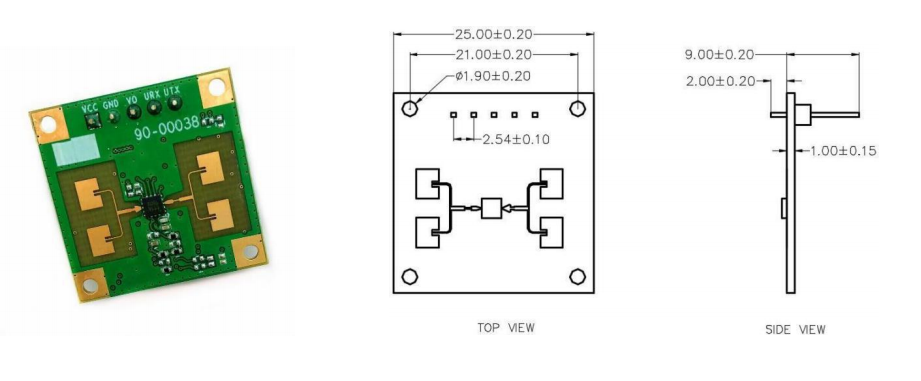
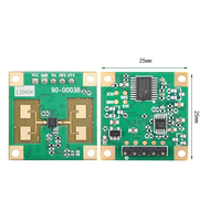
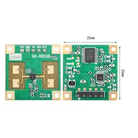
Module size or dimension
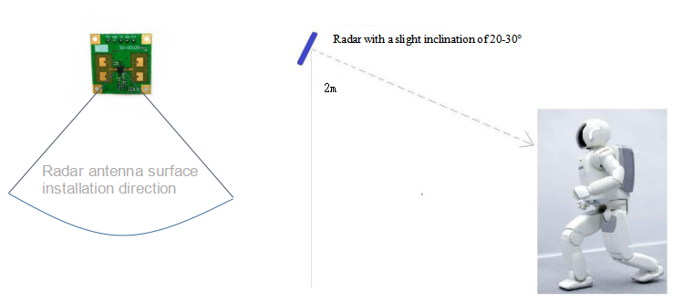
Radar installation and testing
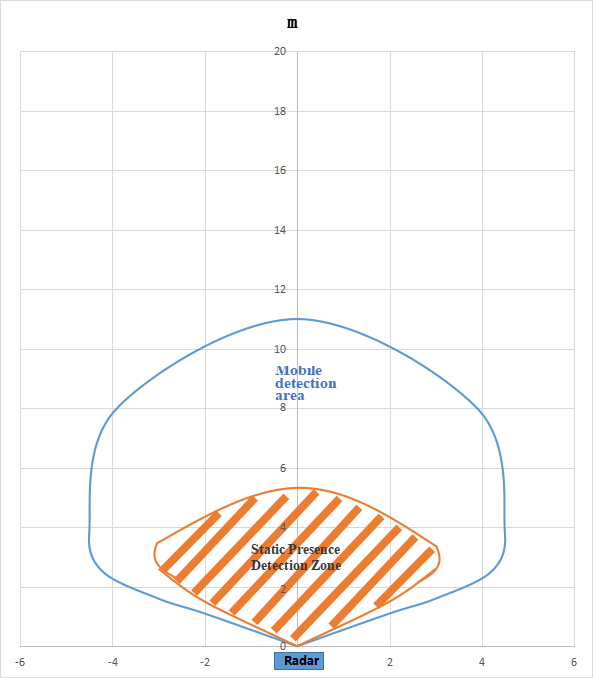
Test Application Scenario 1: Wall Mounting Linear Test The installation height is 2 meters, and the human body is facing the radar when measuring. Test coverage in both standing and walking states. (There will be a test environment display in the appendix)
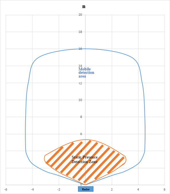
Reference coverage
The figure below shows the radar coverage for stationary standing (orange area) and motion (blue area). for reference. (The left and right range of the blue motion detection is limited by the test site, and only 4.5 meters on the left and right can be measured. The actual coverage may be larger. For details, please refer to the Appendix Test Environment
Reference sensitivity configuration 1:
th1=120 (corresponding to motion detection sensitivity)
th2=250 (corresponding to presence detection sensitivity)
Reference sensitivity configuration 2:
th1=500 (corresponding to motion detection sensitivity)
th2=250 (corresponding topresence detection sensitivity)
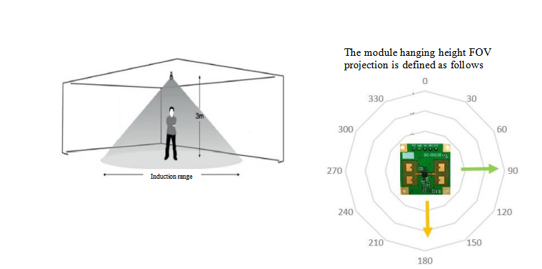
Test Application Scenario 2: Hanging Height Vertical Tes
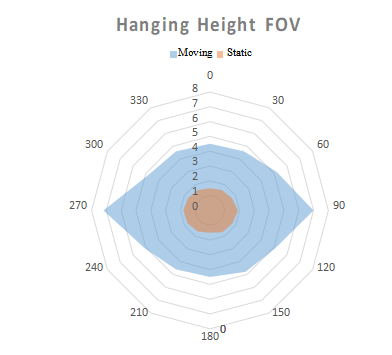
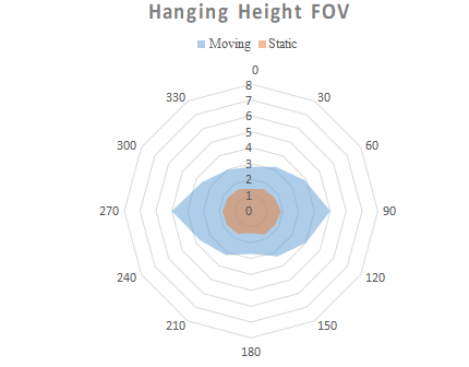
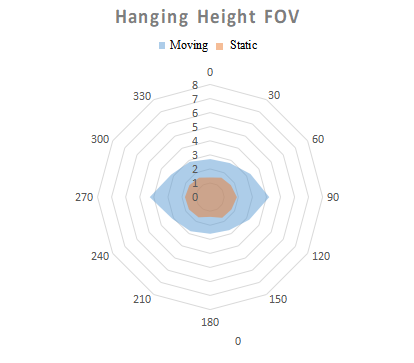
This module can also be hung up for human presence detection. Our test scenario is to hang at a height of 3 meters and measure the FOV of the human body sitting still (orange area) and moving state (blue area). (There will be a test environment display in the appendix)
Reference sensitivity configuration 1:
th1=120 (corresponding to motion detection sensitivity) th2=250 (corresponding to presence detection sensitivity)
Reference sensitivity configuration 2: th1=200 (corresponding to motion detection sensitivity) th2=250 (corresponding topresence detection sensitivity)
Reference sensitivity configuration 3: th1=300 (corresponding to motion detection sensitivity) th2=250 (corresponding topresence detection sensitivity)
Precautions
- When installing, avoid metal and other objects blocking the transmission of electromagnetic waves in front of the module to block the antenna;
- Different shell materials and different distances from the module to the inner surface of the shell will result in different spectral energy returned and parameter settings, which need to be fine-tuned according to actual conditions. It is generally recommended that the module be 5-6mm away from the housing, which can be adjusted according to the actual measurement.
- It is recommended that users test according to the default settings of the module. If the effect is not as expected, the shell structure can be sent to the original factory, and the original factory will carry out the test and adjust a reference setting.
- It is recommended to use plastic as the casing, because the radar is a very sensitive module in the presence of the human body. If the casing is made of a material with high attenuation, it may affect the detection.
- If the person under test sits quietly with his back to the radar, the sensing effect will decrease. Because the back of the radar, the thoracic or abdominal ups and downs caused by breathing cannot be detected at this time.
- Install away from the air conditioner outlet, fan and other objects. Shaking equipment and objects may be detected by radar to determine the presence of persons.
- When multiple modules are installed and used at the same time, the distance between the modules should be greater than 0.5 meters, and at the same time, avoid the antennas of different modules facing each other.
- Sensitivity is adjustable according to user scenarios. Users can adjust the sensitivity according to their actual application scenarios
