Smart presence sensor T19SMWV01: Difference between revisions
Jump to navigation
Jump to search
No edit summary |
|||
| (35 intermediate revisions by the same user not shown) | |||
| Line 12: | Line 12: | ||
Sensor has been designed to have 3 motion / distance sensors that couple together to give an accurate reading of the presence inside one room. | Sensor has been designed to have 3 motion / distance sensors that couple together to give an accurate reading of the presence inside one room. | ||
=== Mechanical design === | |||
{| class="wikitable" | |||
! Design image | |||
! Implementation result | |||
! Thingiverse link | |||
|- | |||
| [[File:T19SMWV01_mechanical.png|thumb|center|400px|T19SMWV01 Mechanical design]] | |||
| [[File:T19SMWV01_mechanical photo.png|thumb|center|400px|T19SMWV01_mechanical photo]] | |||
| https://www.thingiverse.com/thing:3562903 | |||
|- | |||
| colspan="3" | To edit table: [[File:T19SMWV01_mechanical.tng]] | |||
|} | |||
==Specification== | ==Specification== | ||
| Line 22: | Line 34: | ||
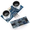
<li style="display: inline-block;"> [[File:HC-SR04 Distance Measuring.jpg|thumb|100px|link=HC-SR04 Distance Measuring Module|HC-SR04 Distance Measuring Module]] </li> | <li style="display: inline-block;"> [[File:HC-SR04 Distance Measuring.jpg|thumb|100px|link=HC-SR04 Distance Measuring Module|HC-SR04 Distance Measuring Module]] </li> | ||
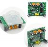
<li style="display: inline-block;"> [[File:HC-SR501 Infrared PIR Motion Sensor Module.jpg|thumb|100px|link=HC-SR501 Infrared PIR Motion Sensor Module|HC-SR501 Infrared PIR Motion Sensor Module]] </li> | <li style="display: inline-block;"> [[File:HC-SR501 Infrared PIR Motion Sensor Module.jpg|thumb|100px|link=HC-SR501 Infrared PIR Motion Sensor Module|HC-SR501 Infrared PIR Motion Sensor Module]] </li> | ||
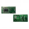
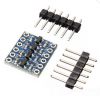
<li style="display: inline-block;"> [[File:Lvl shifter mosfet.jpg|thumb|100px|link=Bi-directional level converter 3V3 5V|Bi-directional level converter 3V3 5V]] </li> | |||
=== Schematic === | |||
[[File:T19SMWV01.jpg|T19SMWV01]] | |||
=== Software === | |||
==== Configuration ==== | |||
{{#snippet:repository=https://github.com/tinel-c/HomieTest.git|filename=platformio.ini|startline=10|endline=20}} | |||
=== IO config sheet === | |||
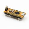
==== Arduino Nano ==== | |||
{| class="wikitable" | |||
! Mapping | |||
! Arduino PIN | |||
! Pin Function | |||
! Serial Pin | |||
! PORT | |||
! Board pin name | |||
! rowspan="16" | [[File:Arduino-Nano-Pinout.jpg|400px|Arduino Nano Pinout]] | |||
! Board pin name | |||
! PORT | |||
! ADC | |||
! Serial Pin | |||
! Arduino PIN | |||
! Mapping | |||
|- | |||
| | |||
| 1 | |||
| | |||
| TXD | |||
| PD1 | |||
| TX1 | |||
| VIN | |||
| | |||
| | |||
| | |||
| | |||
| 5V | |||
|- | |||
| | |||
| 0 | |||
| | |||
| RXD | |||
| PD0 | |||
| RX0 | |||
| GND | |||
| | |||
| | |||
| | |||
| | |||
| GND | |||
|- | |||
| | |||
| | |||
| | |||
| | |||
| PC6 | |||
| RST | |||
| RST | |||
| PC6 | |||
| | |||
| | |||
| | |||
| | |||
|- | |||
| | |||
| | |||
| | |||
| | |||
| | |||
| GND | |||
| 5V | |||
| | |||
| | |||
| | |||
| | |||
| | |||
|- | |||
| | |||
| 2 | |||
| INT0 | |||
| | |||
| PD2 | |||
| D2 | |||
| A7 | |||
| | |||
| ADC7 | |||
| | |||
| A7 | |||
| | |||
|- | |||
| | |||
| 3 | |||
| OC2B / INT1 | |||
| | |||
| PD3 | |||
| D3 | |||
| A6 | |||
| | |||
| ADC6 | |||
| | |||
| A6 | |||
| | |||
|- | |||
| | |||
| 4 | |||
| XCK / T0 | |||
| | |||
| PD4 | |||
| D4 | |||
| A5 | |||
| PC5 | |||
| ADC5 | |||
| SCL | |||
| 19 A5 | |||
| HV1_SCL | |||
|- | |||
| PIR-SIG | |||
| 5 | |||
| OC0B / T1 | |||
| | |||
| PD5 | |||
| D5 | |||
| A4 | |||
| PC4 | |||
| ADC4 | |||
| SDA | |||
| 18 A4 | |||
| HV2_SDA | |||
|- | |||
| | |||
| 6 | |||
| OC0A / AIN0 | |||
| | |||
| PD6 | |||
| D6 | |||
| A3 | |||
| PC3 | |||
| ADC3 | |||
| | |||
| 17 A3 | |||
| | |||
|- | |||
| | |||
| 7 | |||
| AIN1 | |||
| | |||
| PD7 | |||
| D7 | |||
| A2 | |||
| PC2 | |||
| ADC2 | |||
| | |||
| 16 A2 | |||
| | |||
|- | |||
| | |||
| 8 | |||
| ICP1 / CLKO | |||
| | |||
| PB0 | |||
| D8 | |||
| A1 | |||
| PC1 | |||
| ADC1 | |||
| | |||
| 15 A1 | |||
| | |||
|- | |||
| | |||
| 9 | |||
| OC1A | |||
| | |||
| PB1 | |||
| D9 | |||
| A0 | |||
| PC0 | |||
| ADC0 | |||
| | |||
| 14 A0 | |||
| | |||
|- | |||
| | |||
| 10 | |||
| OC1B | |||
| ~SS | |||
| PB2 | |||
| D10 | |||
| REF | |||
| | |||
| AREF | |||
| | |||
| | |||
| | |||
|- | |||
| | |||
| 11 | |||
| OC2 | |||
| MOSI | |||
| PB3 | |||
| D11 | |||
| 3V3 | |||
| | |||
| | |||
| | |||
| | |||
| | |||
|- | |||
| ECHO | |||
| 12 | |||
| | |||
| MISO | |||
| PB4 | |||
| D12 | |||
| D13 | |||
| PB5 | |||
| | |||
| SCK | |||
| 13 | |||
| TRIG | |||
|- | |||
| colspan="13" | To edit table: [[File:Arduino-nano.tgn]] | |||
|} | |||
==== HC-SR04 ==== | |||
{| class="wikitable" | |||
! rowspan="5" | [[File:HC-SR04 Distance Measuring.jpg|center|100px|HC-SR04 Distance Measuring]] | |||
! Pin | |||
! Mapping | |||
|- | |||
| VCC | |||
| POWER_IN | |||
|- | |||
| Trig | |||
| TRIG | |||
|- | |||
| Echo | |||
| ECHO | |||
|- | |||
| GND | |||
| GND | |||
|- | |||
| colspan="3" | To edit table: [[File:HC-SR04.tgn]] | |||
|} | |||
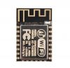
==== ESP8266-12 ==== | |||
{| class="wikitable" | |||
! Mapping | |||
! ADC | |||
! Serial | |||
! Pin | |||
! rowspan="9" | [[File:Esp12.png|center|ESP8266-12]] | |||
! Pin | |||
! Serial | |||
! Mapping | |||
|- | |||
| | |||
| | |||
| | |||
| RESET | |||
| D1 | |||
| TX0 | |||
| | |||
|- | |||
| | |||
| ADC | |||
| | |||
| ADC | |||
| D3 | |||
| RX0 | |||
| | |||
|- | |||
| | |||
| | |||
| | |||
| CHPD | |||
| D5 | |||
| SCL | |||
| LV1_SCL | |||
|- | |||
| | |||
| | |||
| | |||
| D16 | |||
| D4 | |||
| SDA | |||
| LV2_SDA | |||
|- | |||
| LV4_SCK | |||
| | |||
| SCK | |||
| D14 | |||
| D0 | |||
| | |||
| | |||
|- | |||
| | |||
| | |||
| MISO | |||
| D12 | |||
| D2 | |||
| TX1 | |||
| RADAR-SIG | |||
|- | |||
| | |||
| | |||
| RX0* / MOSI | |||
| D13 | |||
| D15 | |||
| SS /TX0* | |||
| | |||
|- | |||
| 3V3 | |||
| | |||
| | |||
| VCC | |||
| GND | |||
| | |||
| GND | |||
|- | |||
| colspan="8" | To edit table: [[File:ESP8266-12.tgn]] | |||
|} | |||
==== Level Shifter ==== | |||
{| class="wikitable" | |||
! Mapping | |||
! Pin | |||
! rowspan="7" | [[File:Lvl shifter mosfet.jpg|200px|Level Shifter]] | |||
! Pin | |||
! Mapping | |||
|- | |||
| HV4_SCK | |||
| HV4 | |||
| LV4 | |||
| LV4_SCK | |||
|- | |||
| | |||
| HV3 | |||
| LV3 | |||
| | |||
|- | |||
| GND | |||
| GND | |||
| GND | |||
| GND | |||
|- | |||
| POWER_IN | |||
| HV | |||
| LV | |||
| 3V3 | |||
|- | |||
| HV2_SDA | |||
| HV2 | |||
| LV2 | |||
| LV2_SDA | |||
|- | |||
| HV1_SCL | |||
| HV1 | |||
| LV1 | |||
| LV1_SCL | |||
|- | |||
| colspan="5" | To edit table: [[File:lvl-shifter-mosfet.tgn]] | |||
|} | |||
Latest revision as of 08:25, 23 June 2019
| Smart presence sensor T19SMWV01 |
|
| https://bogza.ro/index.php/Smart_presence_sensor_T19SMWV01 | |

Description
Sensor has been designed to have 3 motion / distance sensors that couple together to give an accurate reading of the presence inside one room.
Mechanical design
| Design image | Implementation result | Thingiverse link |
|---|---|---|
 |
https://www.thingiverse.com/thing:3562903 | |
| To edit table: File:T19SMWV01 mechanical.tng | ||
Specification
Modules used
Schematic

Software
Configuration
{{#snippet:repository=https://github.com/tinel-c/HomieTest.git%7Cfilename=platformio.ini%7Cstartline=10%7Cendline=20}}
IO config sheet
Arduino Nano
| Mapping | Arduino PIN | Pin Function | Serial Pin | PORT | Board pin name | 
|
Board pin name | PORT | ADC | Serial Pin | Arduino PIN | Mapping |
|---|---|---|---|---|---|---|---|---|---|---|---|---|
| 1 | TXD | PD1 | TX1 | VIN | 5V | |||||||
| 0 | RXD | PD0 | RX0 | GND | GND | |||||||
| PC6 | RST | RST | PC6 | |||||||||
| GND | 5V | |||||||||||
| 2 | INT0 | PD2 | D2 | A7 | ADC7 | A7 | ||||||
| 3 | OC2B / INT1 | PD3 | D3 | A6 | ADC6 | A6 | ||||||
| 4 | XCK / T0 | PD4 | D4 | A5 | PC5 | ADC5 | SCL | 19 A5 | HV1_SCL | |||
| PIR-SIG | 5 | OC0B / T1 | PD5 | D5 | A4 | PC4 | ADC4 | SDA | 18 A4 | HV2_SDA | ||
| 6 | OC0A / AIN0 | PD6 | D6 | A3 | PC3 | ADC3 | 17 A3 | |||||
| 7 | AIN1 | PD7 | D7 | A2 | PC2 | ADC2 | 16 A2 | |||||
| 8 | ICP1 / CLKO | PB0 | D8 | A1 | PC1 | ADC1 | 15 A1 | |||||
| 9 | OC1A | PB1 | D9 | A0 | PC0 | ADC0 | 14 A0 | |||||
| 10 | OC1B | ~SS | PB2 | D10 | REF | AREF | ||||||
| 11 | OC2 | MOSI | PB3 | D11 | 3V3 | |||||||
| ECHO | 12 | MISO | PB4 | D12 | D13 | PB5 | SCK | 13 | TRIG | |||
| To edit table: File:Arduino-nano.tgn | ||||||||||||
HC-SR04
 |
Pin | Mapping |
|---|---|---|
| VCC | POWER_IN | |
| Trig | TRIG | |
| Echo | ECHO | |
| GND | GND | |
| To edit table: File:HC-SR04.tgn | ||
ESP8266-12
| Mapping | ADC | Serial | Pin |  |
Pin | Serial | Mapping |
|---|---|---|---|---|---|---|---|
| RESET | D1 | TX0 | |||||
| ADC | ADC | D3 | RX0 | ||||
| CHPD | D5 | SCL | LV1_SCL | ||||
| D16 | D4 | SDA | LV2_SDA | ||||
| LV4_SCK | SCK | D14 | D0 | ||||
| MISO | D12 | D2 | TX1 | RADAR-SIG | |||
| RX0* / MOSI | D13 | D15 | SS /TX0* | ||||
| 3V3 | VCC | GND | GND | ||||
| To edit table: File:ESP8266-12.tgn | |||||||
Level Shifter
| Mapping | Pin | 
|
Pin | Mapping |
|---|---|---|---|---|
| HV4_SCK | HV4 | LV4 | LV4_SCK | |
| HV3 | LV3 | |||
| GND | GND | GND | GND | |
| POWER_IN | HV | LV | 3V3 | |
| HV2_SDA | HV2 | LV2 | LV2_SDA | |
| HV1_SCL | HV1 | LV1 | LV1_SCL | |
| To edit table: File:Lvl-shifter-mosfet.tgn | ||||